
Brayton/Joule Cycle
Basic Concept:
Gas Turbines are heat engines which produce power by expanding flue gases produced by burning fuels. It consists of a Compressor, Combustion Chamber and Turbine. In a single shaft gas turbine, compressor and turbine are mounted on a single shaft. Gas Turbine works on the Brayton / Joule cycle. An idealized Brayton cycle is shown in the following diagram.
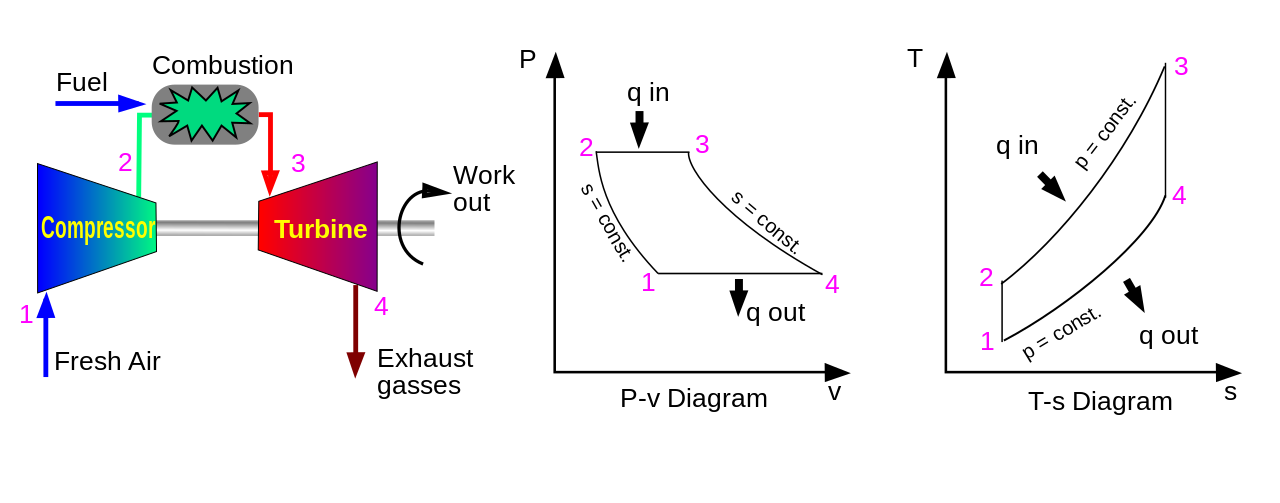
Image: Wikipedia.org
This cycle consists of two Isobaric processes and two Isentropic processes as shown in the diagram. The cycle consist of:
1-2: Isentropic compression in the compressor
2-3: Constant pressure heat addition in combustion chamber
3-4: Isentropic expansion in turbine
4-1: Constant pressure heat rejection
This cycle is similar to Otto cycle which drives SI (spark ignition) engines. The main difference in this two cycles is that, in case of SI engines all the process of compression, combustion and expansion takes place in one cylinder, and in case of Gas turbines, this processes takes place in different components (compressor, combustion chamber and turbine).
Before studying any thermodynamic cycle, studying the physical arrangement of components is very important.
The P-V and T-S diagrams for any thermodynamic cycle can be drawn very easily if the original physical process and its components are well understood.
The P-V and T-S diagrams for any thermodynamic cycle can be drawn very easily if the original physical process and its components are well understood.
In Brayton cycle, fresh air is taken by the compressor through air intake filter, which is compressed in the compressor and delivered to combustion chamber. Fuel is supplied here and the air fuel mixture is ignited with the help of spark plugs to form flue gases, which pass on to turbine section. Flue gases expand here, rotating the Compressor-Turbine rotor. ¾th of the power is consumed in driving the compressor and remaining power is available at the turbine end, which can be used to drive a synchronous generator in generator drive application or to drive a compressor in a mechanical drive application.
Fresh atmospheric air is compressed in the compressor isentropically from state 1-2 increasing its pressure from P1 to P2. As the air is compressed, its temperature also increases from T1 to T2.
Now the air is admitted to combustion chamber, where fuel is supplied. This air fuel mixture is ignited here, heat is added in the process 2-3 by burning of fuel, without significant pressure loss, hence this process is considered to be isobaric heat addition. But in this process temperature of the mixture will increase from T2 to T3, due increase in temperature entropy will also increase from S1 to S2.
Flue gases produced due to combustion of air-fuel mixture in the combustion chamber will pass to the turbine section. Here this gases expand isentropically, shown as process 3-4 in the P-V and T-S diagrams. Due to this expansion, enthalpy of the gases is converted into rotational energy of the turbine rotor. This will reduce the temperature of gases from T3 to T4.
The flue gases coming out of the turbine section have temperatures of the order of 500 degree C. This hot gases are fed into HRSG (Heat Recovery Steam Generator) to utilize the waste heat to produce steam, and finally exhausted to atmosphere. Theoretically turbine exhaust gases are cooled down to compressor Actually this cycle is open cycle, but as the exhaust gases are vented to atmosphere and unlimited supply of fresh is available from atmosphere, this cycle can be considered (theoretically and practically) as closed cycle.
Efficiency of any system can be calculated as ratio of output to the input. Here, heat added in the combustion chamber (Qin) in the process 2-3 is input. Output is the difference between heat supplied (Qin) and heat rejected in the turbine exhaust (Qout).
Therefore,
.png)
}{(T3-T2)} "=\frac {Qin\,-Qout}{Qin} =1-\frac{Qout}{Qin}=1-\frac{(T4-T1)}{(T3-T2)}")
T3 Temperature: The highest cycle temperature in combustion chamber
It can be seen from the above equation that efficiency of the cycle can be unity if the term after minus sign is reduced to zero. But it is not possible by any means. Hence we can increase efficiency by decreasing the term in numerator or increasing the term in the denominator. Decrease in the denominator can be done by increasing T3. T3 is the highest temperature in the cycle which can not be increased beyond a certain limit due to metallurgical limitations of combustion chamber material. This limits the Gas Turbine efficiency. In order to increase T3 temperature, combustion chambers are designed to have counter flow of air and flue gases. By counter flow arrangement, higher T3 temperature can be achieved and hence higher efficiency.
How to increase the power output?
Power output of the gas turbine can be increased by various methods, which can be any one or a combination of the following:
1. By decreasing compressor inlet temperature ( T1 )
2. Regeneration ( heat combustion air by flue gases )
3. Reheat ( in turbine )
4. Inter cooling ( in compressor)
Thermodynamic Analysis:
Fresh atmospheric air is compressed in the compressor isentropically from state 1-2 increasing its pressure from P1 to P2. As the air is compressed, its temperature also increases from T1 to T2.
Now the air is admitted to combustion chamber, where fuel is supplied. This air fuel mixture is ignited here, heat is added in the process 2-3 by burning of fuel, without significant pressure loss, hence this process is considered to be isobaric heat addition. But in this process temperature of the mixture will increase from T2 to T3, due increase in temperature entropy will also increase from S1 to S2.
Flue gases produced due to combustion of air-fuel mixture in the combustion chamber will pass to the turbine section. Here this gases expand isentropically, shown as process 3-4 in the P-V and T-S diagrams. Due to this expansion, enthalpy of the gases is converted into rotational energy of the turbine rotor. This will reduce the temperature of gases from T3 to T4.
The flue gases coming out of the turbine section have temperatures of the order of 500 degree C. This hot gases are fed into HRSG (Heat Recovery Steam Generator) to utilize the waste heat to produce steam, and finally exhausted to atmosphere. Theoretically turbine exhaust gases are cooled down to compressor Actually this cycle is open cycle, but as the exhaust gases are vented to atmosphere and unlimited supply of fresh is available from atmosphere, this cycle can be considered (theoretically and practically) as closed cycle.
Efficiency:
Efficiency of any system can be calculated as ratio of output to the input. Here, heat added in the combustion chamber (Qin) in the process 2-3 is input. Output is the difference between heat supplied (Qin) and heat rejected in the turbine exhaust (Qout).
Therefore,
Limitations of Brayton Cycle / How to increase efficiency?
T3 Temperature: The highest cycle temperature in combustion chamber
It can be seen from the above equation that efficiency of the cycle can be unity if the term after minus sign is reduced to zero. But it is not possible by any means. Hence we can increase efficiency by decreasing the term in numerator or increasing the term in the denominator. Decrease in the denominator can be done by increasing T3. T3 is the highest temperature in the cycle which can not be increased beyond a certain limit due to metallurgical limitations of combustion chamber material. This limits the Gas Turbine efficiency. In order to increase T3 temperature, combustion chambers are designed to have counter flow of air and flue gases. By counter flow arrangement, higher T3 temperature can be achieved and hence higher efficiency.
How to increase the power output?
Power output of the gas turbine can be increased by various methods, which can be any one or a combination of the following:
1. By decreasing compressor inlet temperature ( T1 )
2. Regeneration ( heat combustion air by flue gases )
3. Reheat ( in turbine )
4. Inter cooling ( in compressor)
No comments:
Post a Comment
Was this helpful?
Do you have any questions?
Need any further assistance for the topic?
Please leave feedback!